

Roof beams
Pitched aluminium members with four open corner channels for the PVC. The hollow section and fixing holes receive the eave and ridge knuckles.
From complete aluminium frames to additional bays and replacement parts, explore our span range, extrusion profiles and the components that bring a clearspan marquee together.
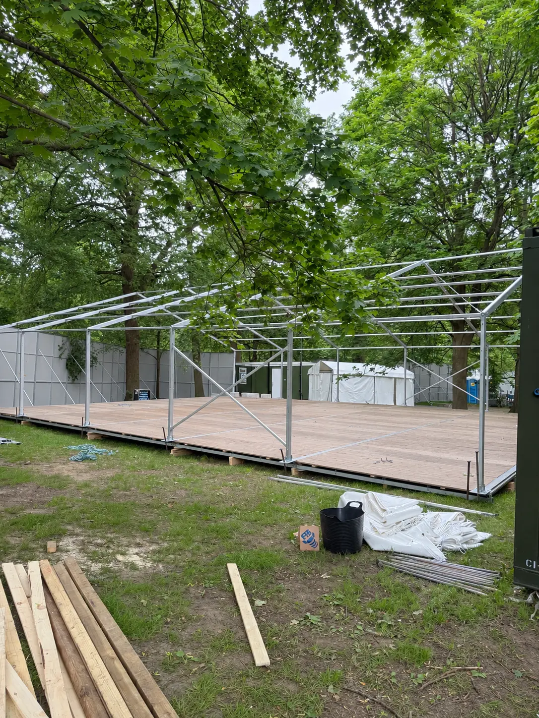
Choose a 3, 6, 9, 12 or 15 m width. Lengths extend in 3 m bays, with eave heights of 2.3 m or 3 m across our standard range.
End-gable supports are shown at 3 m centres. These are end-wall legs; the space between the main frames remains clear of internal columns. All five diagrams use the same metre scale.
Four 3 m bays create a 12 m length; six create 18 m. For example, a 9 × 18 m marquee gives a 162 m² footprint. We can discuss a complete structure, additional bays or individual replacement components.
Explore structure dimensionsThe frame range includes 94 × 48 mm and the larger 114 × 80 mm aluminium sections. The profile is specified to suit the frame, span and connection arrangement.
Four open PVC channels around a hollow core.
A larger section with visible internal reinforcing ribs.
Both profiles are illustrated at the same scale, with the open PVC channels and internal shapes shown. Dimensions are nominal; confirm the exact section and matching fittings when ordering.
| Section | First dimension | Second dimension |
|---|---|---|
| 94 × 48 mm | 94 mm | 48 mm |
| 114 × 80 mm | 114 mm | 80 mm |
Explore the members, connectors and bracing that make up the system. Each part has a role in the complete frame assembly.
Pitched aluminium members with four open corner channels for the PVC. The hollow section and fixing holes receive the eave and ridge knuckles.
Open aluminium uprights with continuous PVC channels, elongated connection slots and round fixing holes. Slot arrangements depend on the leg and eave-height specification.
Members joining neighbouring frames at eave level. The shaped section includes lower attachment channels, with a curved flat hook fixed beneath each end.
Hollow box-section members linking frames at the ridge and along the roof slopes. Bent flat end hooks locate the purlins; their number and positions follow the frame specification.
Rails used to hang and slide compatible PVC sidewalls. Specify the bay length and connection details when ordering replacements.
Round tubular rails with flat fixing ends, running at ground level between the legs. Match the length and end connections to the wall and frame arrangement.
A continuous perforated hollow insert with its fitted bottom cap for the intermediate gable leg. The series of fixing holes allows the specified connection position to be selected.
Angled steel connectors joining the upright leg to the pitched roof beam. The illustration shows the fixing holes, elongated slot and connection eye.
Two angled arms joining the roof beams at the apex, with the central purlin fitting and connection eye shown separately from the aluminium beam section.
Crossed braces fitted in the specified side bays. Bracing positions are coordinated with doors and openings; portal arrangements are available where specified.
Horizontal members with upright angle brackets at both ends. A specified portal arrangement can keep a side opening clear where scissor bracing would otherwise cross it.
Slim plates with three anchoring holes, two upright cheeks and a transverse retaining pin. The leg sits between the cheeks; anchoring is selected for the frame and site.
Tensioned wire assemblies used in the specified bracing positions. End fittings and tensioning components form part of the complete assembly.
Illustrations show the component details; lengths may be shortened to make the connections clear. Confirm sizes, end fittings and bracing positions for your frame before ordering.
Our Pontefract workshop supports our own hire stock and other marquee operators. Talk to us about new frames, matching bays, replacement legs, roof members and fittings.